
View Our Recent Work:

Yes, a competent DIYer can install an inverter charger, provided they respect three unforgiving details: DC cable and fuse sizing, neutral to ground bonding during transfer, and mechanical mounting with real airflow around the unit. Get those three right and the rest of the job is patient, methodical work. Get any one wrong, and you either burn a cable or hand a code inspector a reason to fail your boat or rig. If your setup involves 24V or 48V banks, a generator handoff, or ABYC certification for resale, that is the point to call a marine electrician instead of pushing through alone.
TL;DR:
- Proper inverter charger installation demands exact sizing of cables, fuses, and battery bank capacity based on load calculations and battery chemistry.
- Mounting must respect manufacturer clearance, ventilation, and safety barriers, especially near batteries to prevent gas buildup and heat damage.
- Correct neutral to ground switching and transfer relay operation are critical to avoid ground faults or dangerous ground loops.
- Using marine-grade tinned copper cable and tightly torqued lugs reduces corrosion risks and electrical resistance for long-term reliability.
- When in doubt on complex setups or high-voltage systems, hiring a professional marine electrician ensures compliance with ABYC standards and safe operation.
Table of Contents
- What Does an Inverter Charger Install Actually Involve?
- Tools, Cable, and Safety Gear You Need Before You Start
- Where Should You Mount the Inverter Charger?
- How Do You Size DC Cable, Fuses, and Lugs Correctly?
- How Do You Wire AC Circuits and Handle the Neutral to Ground Bond?
- How Do You Integrate Shore Power and a Generator Safely?
- What Tests Confirm the Install Is Safe to Use?
- What Safety Codes Apply, and When Should You Hire a Professional?
- Common Symptoms, Likely Causes, and Quick Fixes
- What I’ve Learned Watching These Installs Go Wrong
- Prefer a Certified Marine Electrician to Handle It?
- Where to Verify the Technical Details Yourself
What Does an Inverter Charger Install Actually Involve?
An inverter charger install is really two jobs stitched together: sizing a DC power system that can feed the unit under real load, and wiring an AC system that behaves safely no matter which power source (shore, generator, or the inverter itself) happens to be live. Most people searching “inverter charger install” already know what the box does. The challenge usually lies in the math and adhering to electrical codes rather than the concept itself.
Start with the load. Walk through every appliance you plan to run simultaneously and note both its continuous wattage and its surge (startup) wattage, since a refrigerator compressor or a microwave magnetron can pull two to three times its rated draw for a second or two on startup. Add those continuous loads together, then check that your inverter’s surge rating comfortably covers your worst-case simultaneous startup event. A good rule of thumb is to size the inverter around 20% above your calculated continuous load, not right at the edge of it.
Battery capacity follows a different kind of math. A 400 amp-hour bank sounds generous until you realize lithium banks are typically rated for use down to 20% remaining charge, while older AGM banks are often derated to 50%, cutting your usable capacity roughly in half. Divide your daily watt-hour draw by your usable amp-hours times system voltage, and you will quickly see whether your bank is undersized for a weekend away from shore power.
- Convert every appliance’s running watts and surge watts before picking inverter size, not after.
- Add a margin, typically 20%, above your worst realistic simultaneous load.
- Calculate usable amp-hours based on your battery chemistry’s safe discharge floor, not total rated capacity.
- Consider 24V or 48V systems once continuous draw climbs past roughly 2,000 to 3,000 watts, since higher voltage cuts amperage and therefore cable gauge dramatically for the same power.
- Treat manufacturer manuals and ABYC E-11 load calculation methods as the final word on sizing, not a blog post or a forum thread.
Higher system voltage is the quiet fix most DIYers overlook. Doubling your battery voltage from 12V to 24V halves the current needed for the same wattage, which means you can often drop from 4/0 cable to 2/0 or even 1/0, saving weight, cost, and voltage drop in one move.
Tools, Cable, and Safety Gear You Need Before You Start
Half the frustration in an inverter charger install comes from stopping mid-job to drive to a marine supply store. Gather everything first.
Tools worth owning rather than borrowing include a torque wrench rated for small fasteners, a quality digital multimeter, a hydraulic or ratcheting lug crimper sized to your cable gauge, a DC current clamp meter, and a heat gun for shrink tubing. For materials, buy marine-grade tinned copper cable rather than standard automotive cable, since tinning resists the corrosion that untinned copper suffers in humid or salt-laden air. Pair it with properly rated lugs, a Class T fuse or appropriately rated DC breaker, and adhesive-lined heat shrink for every crimped joint.
- Torque wrench, digital multimeter, DC-rated crimper, current clamp meter, heat gun
- Tinned marine-grade copper cable in the gauge your load calculation demands
- Class T fuses or DC breakers, rated lugs, and adhesive-lined heat shrink
- Eye protection, insulated gloves, and a plan for battery gas ventilation during work
Pro Tip: If your crimper cannot deliver a proper hydraulic crimp on 2/0 or larger cable, buy pre-lugged cable or pay a cable shop to crimp your battery leads. A cold crimp on a large-gauge lug is one of the most common causes of a fire in an otherwise well-planned system.
Where Should You Mount the Inverter Charger?
Location decisions get rushed because the unit is heavy and awkward, and that is exactly when mistakes happen. Manufacturer manuals consistently specify clearance zones front and rear for airflow, since these units cool themselves by pulling air across internal heat sinks, and blocking that path triggers thermal shutdown under load.
Keep DC cable runs short to limit voltage drop, but do not mount the inverter directly over the battery bank unless a gas-impermeable barrier separates the two. Charging batteries, especially flooded lead-acid types, vent hydrogen, and an inverter’s internal fan or relay contacts sitting right above that gas is a bad combination. Manufacturer installation excerpts specifically warn against standing-water locations and call for mounting hardware capable of holding at least twice the unit’s weight, since vibration on a boat or moving RV works fasteners loose over time.
- Respect the manufacturer’s minimum clearance on all ventilated sides, not just the front.
- Balance short DC runs against safe separation from battery off-gassing.
- Never mount directly above a battery bank without a sealed, gas-impermeable barrier.
- Use stainless or otherwise corrosion-resistant fasteners rated for at least double the unit’s weight.
Orientation matters too. Most units are designed to breathe front-to-back or bottom-to-top, and mounting one sideways or upside down without checking the manual can quietly starve it of airflow for years before you notice the derating.
How Do You Size DC Cable, Fuses, and Lugs Correctly?
This is where an inverter charger install lives or dies. The industry target is a 3% voltage drop between battery and inverter at full load, and that percentage, not a generic “bigger is better” instinct, is what should set your cable gauge. A DC wire sizing calculation run against your amperage and one-way cable length will tell you exactly which gauge keeps you under that threshold.
Consider a 3,000 watt, 12V inverter under full continuous load. At 12V, 3,000 watts draws roughly 250 amps continuously, and surge current during appliance startup can spike well beyond that. That amperage is why these installs demand 4/0 cable and fuses rated in the 300 to 400 amp range even for runs of just a few feet. Undersized cable at that current does not just waste power to heat. It can melt insulation or start a fire.
Follow this sequence for the DC side:
- Calculate your continuous and surge amperage from the inverter’s rated wattage and battery voltage.
- Select cable gauge that keeps voltage drop under 3% for your actual one-way run length.
- Install the DC positive fuse or breaker within 18 inches of the battery terminal, sized to meet or exceed the inverter’s minimum DC fuse rating with adequate interrupting capacity (AIC) for available short-circuit current.
- Crimp lugs with a properly sized hydraulic or ratcheting tool, seal every joint with adhesive-lined heat shrink, and torque terminal connections to the manufacturer’s stated spec, not by feel.
That 18-inch rule is not arbitrary. It exists because an unfused length of cable between the battery and the first protective device is a length of wire that can carry a dead short with nothing to stop it until something else melts, arcs, or catches fire.
Terminal torque deserves the same respect as cable gauge. An under-torqued lug creates resistance, resistance creates heat, and heat at a battery terminal is how good installs quietly become fire hazards months later.
How Do You Wire AC Circuits and Handle the Neutral to Ground Bond?
AC wiring on an inverter charger install introduces a problem DC work never has: multiple possible power sources feeding the same panel, and each one needs to see a single, correctly bonded neutral to ground connection, never two at once.
Start with the basics. Match your AC input wire gauge to the upstream breaker rating, whether that breaker lives at the shore power pedestal, the generator panel, or your main AC distribution panel. Most inverter chargers include either an internal transfer relay or expect an external one, and that relay’s real job is bigger than just switching power sources. It has to switch the neutral to ground bond along with it.
Here is why that matters. When shore power is connected, the neutral and ground are bonded back at the utility transformer or generator, so your vessel or RV should avoid creating a second bond point. But when the inverter is the only source (running on batteries, disconnected from shore or generator), something has to establish that bond locally, or you lose ground fault protection entirely. Technical guidance on neutral to ground switching explains that this switching has to be automatic and tied to transfer relay position, never left to a manual switch someone might forget to flip.
- Wire AC input conductors sized to the upstream breaker, never smaller, regardless of run length.
- Confirm your transfer relay (internal or external) switches the neutral to ground bond in sync with power source, not independently.
- Place GFCI protection downstream of the transfer point so it sees whichever source is actually live.
- Never allow shore power and inverter mode to both maintain an active neutral to ground bond simultaneously.
Get the bonding wrong and you get one of two failure modes. Either you lose ground fault protection entirely and a fault current has nowhere safe to go, or you create a ground loop that trips your GFCI every few minutes for no obvious reason. Both are dangerous, and the second one is just annoying enough that people start disabling GFCI protection to make it stop, which is exactly the wrong move.
Pro Tip: If your GFCI trips only when running on the inverter but never on shore power, suspect a double bond or a miswired transfer relay before you suspect a bad GFCI outlet. Swapping the outlet rarely fixes a bonding problem.
How Do You Integrate Shore Power and a Generator Safely?
Once you add a generator to a boat or RV that already has shore power and an inverter charger, you have three possible sources feeding one panel, and the wiring topology needs to make it physically or electrically impossible for two of them to connect at once.
A basic shore-only setup is simple: one inlet, one breaker, one bond point. Add a generator and you need a transfer mechanism, either an automatic transfer switch or the inverter’s own internal relay logic, that guarantees only one source powers the panel at any moment. Add the inverter as a third source and that transfer logic has to arbitrate between all three, prioritizing shore or generator over battery power whenever either is available and healthy.
- Confirm your shore power inlet and feeder cable ampacity match your panel’s maximum draw, not just your inverter’s rating.
- Test generator handover by starting the generator with shore power connected and confirming the transfer switch drops shore before generator ties in.
- Upgrade inlet and feeder gauge before upgrading generator size, since an underrated inlet becomes the bottleneck.
- Label every breaker, inlet, and transfer switch clearly, and keep a laminated wiring diagram onboard for future service work.
Mechanical interlocks matter more than people expect. A transfer switch that is electrically correct but lacks a mechanical interlock preventing simultaneous source connection is one wiring mistake away from backfeeding a generator into a shore pedestal, which can injure a dockworker or damage equipment on a neighboring boat.
What Tests Confirm the Install Is Safe to Use?
Commissioning is not optional, and skipping it is how “it worked fine at the dock” becomes “it caught fire three weeks later at anchor.” Work through these checks in order, every time.
- Dead-check every circuit with power disconnected before touching a single terminal.
- Verify DC continuity and confirm every fuse is present and rated correctly before applying battery power.
- Power on the inverter with no AC load connected and confirm stable output voltage on your multimeter.
- Apply a small known AC load and verify output voltage and frequency stay within spec under your clamp meter.
- Simulate a source transfer (disconnect shore, start generator, or switch to inverter-only) and confirm the neutral to ground bond switches correctly each time.
Watch for red flags at every step: unexpected voltage readings, warm terminals after even brief operation, or a GFCI that trips the moment you switch sources. Any of those means stop and investigate before continuing, not push through and hope it settles down.
Write down your torque values, breaker positions, and inverter configuration settings once everything checks out. Future troubleshooting, and any warranty claim, depends on knowing exactly how the system was set up on day one.
What Safety Codes Apply, and When Should You Hire a Professional?
Marine and RV installs share a lot of DNA but diverge in ways that matter. Boats demand tinned cable, higher-temperature insulation, and sealed terminations because salt air and bilge moisture attack untinned copper in ways an RV underbelly never sees. Marine-specific installation guidance treats these as non-negotiable, not optional upgrades.
ABYC standards evolve too, and recent updates to case-ground conductor sizing under ABYC A-31 mean the ground conductor for an inverter charger may now be sized relative to the unit’s own DC overcurrent protection instead of strictly mirroring the main battery cable. If you are not tracking standard revisions, this is exactly the kind of detail that gets missed.
- Moving from 12V to 24V or 48V systems, since cable sizing, fusing, and component compatibility all change.
- Any install involving shore power plus a generator plus an inverter, where transfer logic gets genuinely complex.
- Needing ABYC certification for insurance, survey, or resale purposes.
- Uncertainty about neutral to ground bonding on a vessel you did not wire from scratch.
A boat’s electrical system has to survive years of vibration, salt air, and moisture that a house or RV underbelly never faces, and that is exactly why marine wiring rules exist as a separate, stricter standard rather than a suggestion.
If any of those triggers apply, Mazzamarine’s marine electrical team handles the install to ABYC standard, documents it properly, and leaves you with a system a surveyor will actually sign off on.
Common Symptoms, Likely Causes, and Quick Fixes
Most inverter charger problems trace back to one of a handful of usual suspects, and a methodical check saves you from replacing a perfectly good unit.
- No AC output at all: check the DC fuse first, since a blown fuse near the battery is the single most common cause.
- Inverter runs but shuts down under load: suspect undersized cable causing excessive voltage drop, or a loose terminal creating resistance heat.
- GFCI trips repeatedly on inverter power only: suspect a miswired or unsynced neutral to ground bond, not a bad outlet.
- Charger won’t bring the battery bank to full charge: check charge profile settings against your battery chemistry, since a lead-acid profile on a lithium bank undercharges it.
Pro Tip: Isolate wiring faults from component faults by testing with a known-good load, like a simple resistive heater, before assuming the inverter itself is defective.
Stop immediately and call a professional if you smell burning insulation, see scorch marks near any terminal, or find a breaker that trips instantly on reset. Those symptoms mean something failed under load, and restarting the system before finding the cause risks a repeat failure that is worse the second time. Beyond troubleshooting, plan a semiannual check of terminal torque and cable condition, since vibration loosens connections gradually and salt air corrodes exposed metal faster than most owners expect.
What I’ve Learned Watching These Installs Go Wrong
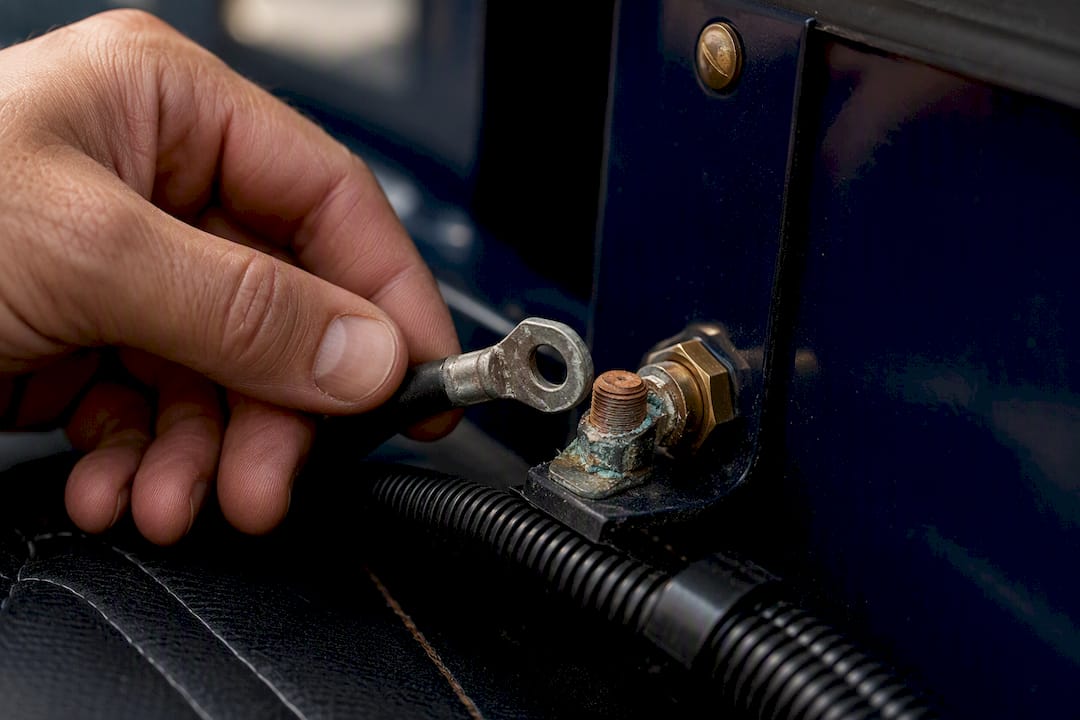
The mistake I see most often isn’t bad wiring. It’s an owner who buys the inverter and the cable on the same day and starts cutting before checking whether the lugs they grabbed actually match the cable gauge. Pre-order the exact lug sizes before you touch a saw. Plan your cable route on paper, standing in the actual space, before you mount anything, because a route that looks obvious on a workbench often has to snake around a fuel line or a bulkhead you forgot about. And keep a written log of every torque value and setting. It feels like busywork until the day something needs troubleshooting and that log turns a two-hour diagnosis into a ten-minute one.
— Jason
Prefer a Certified Marine Electrician to Handle It?

Before requesting service, have your boat or RV model, the inverter/charger model number, and your battery bank specs (voltage, chemistry, and amp-hour rating) ready. That lets the team quote accurately and show up with the right cable gauge and hardware already on the truck. A typical engagement includes a wiring diagram, a torque log for every DC and AC connection, and a written commissioning report confirming transfer and bonding behavior under test, the same records a good DIY installer should keep but rarely has time to format properly. If your project extends into broader system work, from marine electrical upgrades to a full maintenance package, the same team can scope it in one visit. Reach out through Mazzamarine’s service page with your boat’s details, and get a quote before your next haul-out or storage season.
Where to Verify the Technical Details Yourself
Before finalizing any install, check your inverter’s own installation manual, the relevant ABYC E-11 excerpts, and NEC sections covering RV or marine wiring. These sources carry the exact wire tables, fuse placement rules, and transfer requirements your specific system needs.
Recommended
Text or Call 954-330-9653 Schedule Appointment
Mazza Marine Yacht Services & Refit

Fiberglass Upgrades and Damage Repair

Premium Yacht Paint/ Faux Teak

Fishing: Custom Rods, Reels,Tackle

Electrical, Electronics and Navigation

Paint, Hull and Gelcoat

Teak Decks, Wood Cabinets, Carpentry

Canvas, Enclosures and Upholstery

Mechanical, Repower and Running Gear

Plumbing, Bilge and Thru-Hulls

Welding and Custom Fabrication

Interior Refit And Past Work
Get your yacht value Estimate
"*" indicates required fields